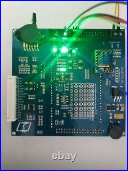
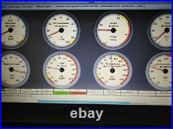
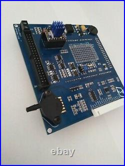
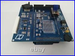
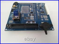
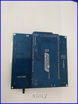

FIRMWARE, ignition & injection map. Total probedd 100% functionality to TunerStudio. Only for motors with inductive ckp & cmp sensor. With sixteen auxiliary outputs. Does not include installation. General recommendations on installation, do not skip this point, it is very important. Before starting with the ECU connection, you will see some general recommendations on how to carry out the electrical installation. Ignition and electronic injection systems can give many problems due to electromagnetic interference if some considerations are not taken into account, all of them are equally important, once a problem occurs it is very difficult to diagnose, please follow these indications. Symptoms are battery voltage spikes, sensor signal noise, unstable rev signal, loss of connection between ECU and PC, all of which cause frustration for the user. Read carefully and try to do a good job on your installation, with this you will be happy and do not go crazy looking for electronic ghosts. Do not connect the masses to the chassis or body, the masses must be on the engine block, if possible at the same point where the battery ground to the engine. The battery usually has two cables connected to its negative terminal, one of them to the chassis and the other to the engine block, it is at that point of the engine block where you want to connect the ECU ground. If you have previously changed the location of the battery, you must run a cable from it to the engine block, in the same way that it was connected as standard, if the route you must take is long, try to put a cable thicker than the series. Clean this point of paint, grease or dirt well before connecting the masses. Don’t bundle all pins marked ground on one wire and lead it to the block. From each pin indicated as ground in the ECU connector you must put a direct wire to the point chosen as ground, at that point you can join all the wires in a terminal and screw to the block. Separate the ECU wiring from the rest of the vehicle wiring, alternator cables, starter motor, etc… All these cables have a high energy consumption and can create interference in the injection and ignition system that is very difficult to diagnose. It is even convenient to separate the wiring of the ECU itself that connects to the coils and their grounds from the rest of the wiring, as you will see we have tried to separate these connections in all our units when possible. The ignition coils have a high energy consumption, between 6 and 8 Amps compared to a few milliamps consumed by the ECU itself, in addition to this the pulsations that activate and deactivate the coils, along with their high intensity, are by themselves a source of trouble, try routing this wiring and its grounds in a different location than the ECU power and sensor wiring. Prevent the ECU wiring from passing near any engine component that produces electromagnetism, has a high energy consumption or works with very high voltages, starter motor, alternator, ignition coils, spark plug cables, etc… Check the good condition of the alternator, starter motor, ignition coils, spark plug cables, etc… Many of the problems that we have encountered in installations are caused by a malfunction of some of these components. Do not use spark plug wires like those used in carburetion systems, they do not have any protection against interference, always install spark plug wires that work with injection systems and check their condition. Diameter of the wiring and its distribution, if you have bought an automotive wiring in our store, you will see that it has cables of two different diameters, they are designed for the consumption of each component. If you are using a USB to RS232 adapter install a DB9 to DB9 cable or connect three cables (preferably shielded) into the connector and use the adapter directly on the PC. If you connect the adapter directly to the ECU, communication with the PC may be lost at any time. The wide band connection is usually made through 4 cables in most cases, nowadays 3 cables in most: -Power supply + 12V, it is advisable that the probe is not put into operation until the engine is running, if this happens, condensed water could reach the exhaust or unburned gasoline from the starter into the probe and destroy it. For this reason, we recommend connecting the probe supply to the fuel pump relay, this will only activate when the engine is running. Electronic mass, it is the mass of the internal electronic circuit, it must go to the same point as the mass of the ECU, with a separate wire to the block. Heater mass, today’s systems have the electrical and heater mass together, so they will only have one mass. If it exists, it is better to carry this mass on a separate cable to the engine block. The item “Standalone full SMD Engine ECU” is in sale since Tuesday, September 29, 2020. This item is in the category “Motor\ piezas y accesorios\Coches\ tuning y styling\Chip tuning y tuning del motor\ECUs/Centralitas”. The seller is “sermed-65″ and is located in SANT JOAN DE VILATORRADA. This item can be shipped worldwide.
- Color principal: Azul
- Marca: – Sin marca/Genérico -
- Modelo: SPEEDUINO
- MPN: No aplicable

